This module takes the outputs from the various sensors within the Amplifier & RF Sampler modules , together with the request to change over from receive to transmit ( PTT ) to actually operate the changeover relays .This module can be either " Analog " using comparators & discrete logic or " Digital " using a microprocessor , in order to speed up the commissioning of the completed amplifier the analog route was taken .
The alarm levels are set within this module to protect the RF Power amplifier from Over Temperature , High VSWR ( Poor Return Loss ) together with status indicators for each alarm condition. The amplifier's heatsink temperature is measured using the LM35 sensor this gives an output of 10mV / Deg C ,so that it is possible to arrange for both speeding up of the fans from their normal rate to assist in cooling the amplifier as well as the amplifier module. If the temperature exceeds a second alarm value then this can be used to inhibit the transmit enable line using simple voltage comparators with open collectors in a " Wired OR " configuration.
The " Push To Talk " line on the transmitter is also fed in to a comparator to check the state of the system ,due to the need to accomodate more than one switching threshold value (some transitters use a 12 volt PTT line others use + 8 volts in the receive state) the switching threshold with some limited hysteresis was set to 5 volts , less than this value was taken as a " Transmit " instruction , provided none of the alarms were activated , the amplifiers' relays changed over then the RF was applied there being a slight delay in the changeover back to receive to minimise any residual RF power damaging the contacts of the output relay . The relative alarm states are indicated by LED's Yellow being a warning state and with Red for a fault condition .So for instance if the fans are running fast due to it being a high ambient temperature it will show a Yellow indication , but high VSWR causing the protection circuits to act will show a Red indication and inhibit the transmit changeover line.
Future work may include the replacement of the " Analog " control module with a PIC microprocessor based design , based on the Arizona microchip 16F87X
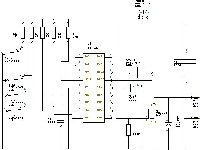
Circuit of the Control Board
Artwork for Control & Monitoring PCB Top Copper ( Mirrored )
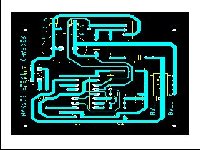
Artwork for Control & Monitoring PCB Bottom Copper

Component Overlay for Control & Monitoring PCB
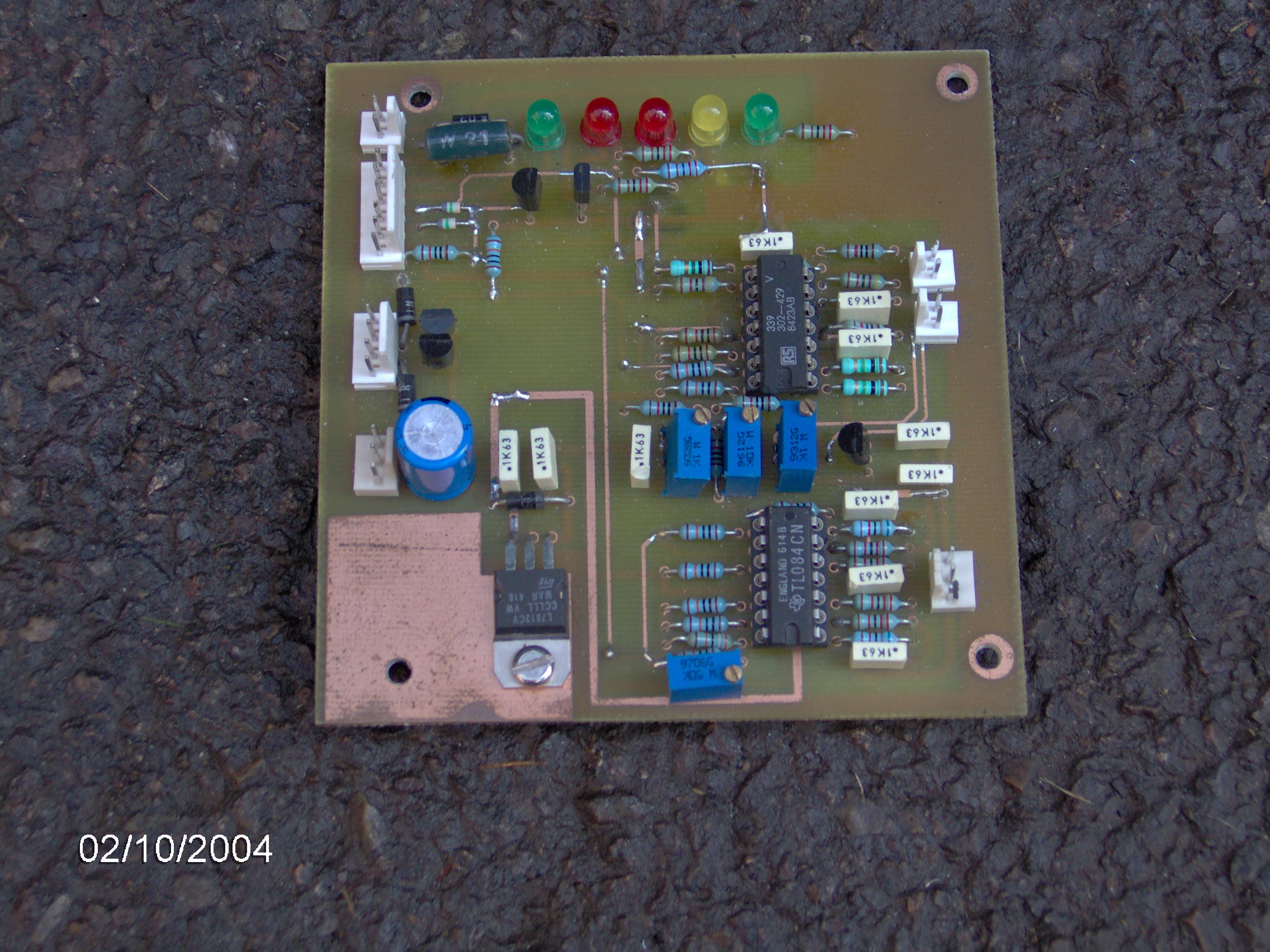
Picture of the completed Control Board
Circuit of the Display Board for the controller
Artwork for Display PCB
Component overlay for Display PCB
This page last updated 10th Oct 2009