This range of dual directional couplers was designed using Microwave Office to be used with the " Pic Based Power meter " and other test gear . The coupling factor was designed to allow the power meter to read up to 100 Watts as per the " Tap" attenuator described in the ARRL handbook ie about 40dB , the couplers were then optimised for each of the VHF / UHF amateur radio bands ( 2m , 70cm & 23cm ) they have been designed to fit in to a " standardised " housing to keep manufacturing costs down . The housing is machined from an Aluminium block to ensure rugged & reliable performance for many years use.
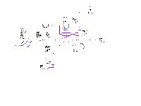
The Schematic of the Dual coupler as modelled with Microwave Office
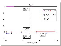
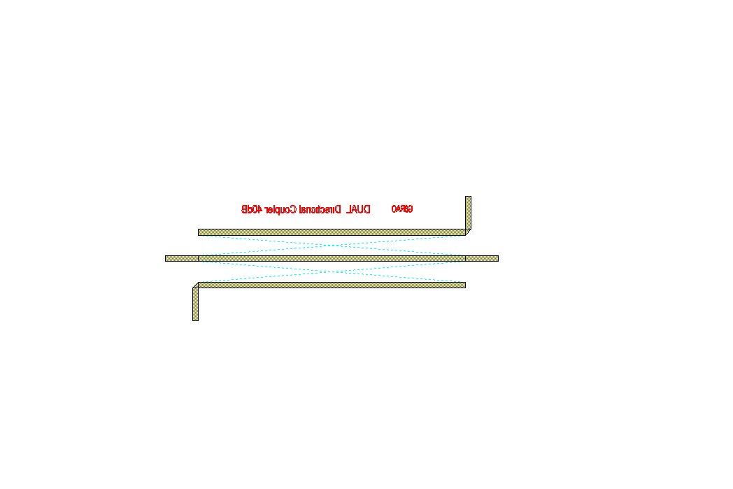
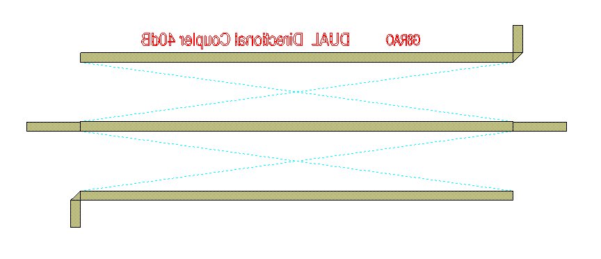
The frequency response of the Dual coupler as modelled in Microwave Office
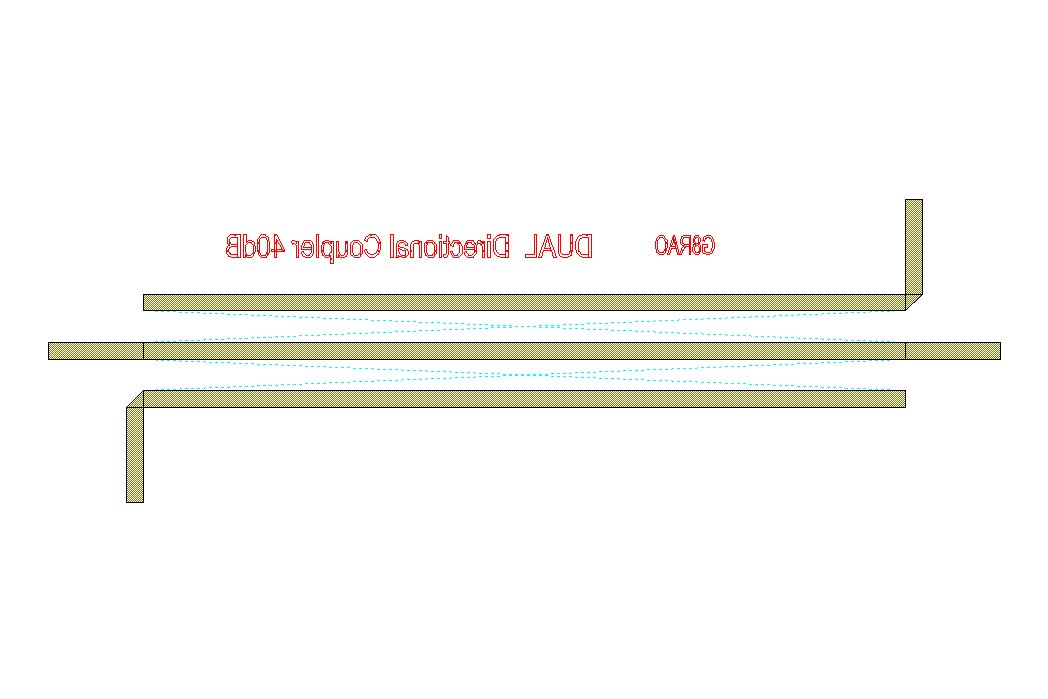
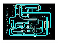
The completed artwork from Microwave Office
The Schematic of the Dual coupler as modelled with Microwave Office
The frequency response of the Dual coupler as modelled in Microwave Office
The completed artwork from Microwave Office
The Schematic of the Dual coupler as modelled with Microwave Office
The frequency response of the Dual coupler as modelled in Microwave Office
The completed artwork from Microwave Office
Mirrored Artwork for both 145 MHz Coupler , 435MHz Coupler & 1296 MHz Coupler
The General Assembly Drawing , housing & cover drawings are common to 145 & 435MHz frequency variants, only the PCB is changed to suit each band variant however the 1296 MHz version the line length was becoming a significant part of the wave length so a shorter box is required to go with the shorter coupled line lengths.
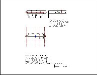
The Coupler body ( Low frequency variant )
The Coupler cover (Low frequency variant )
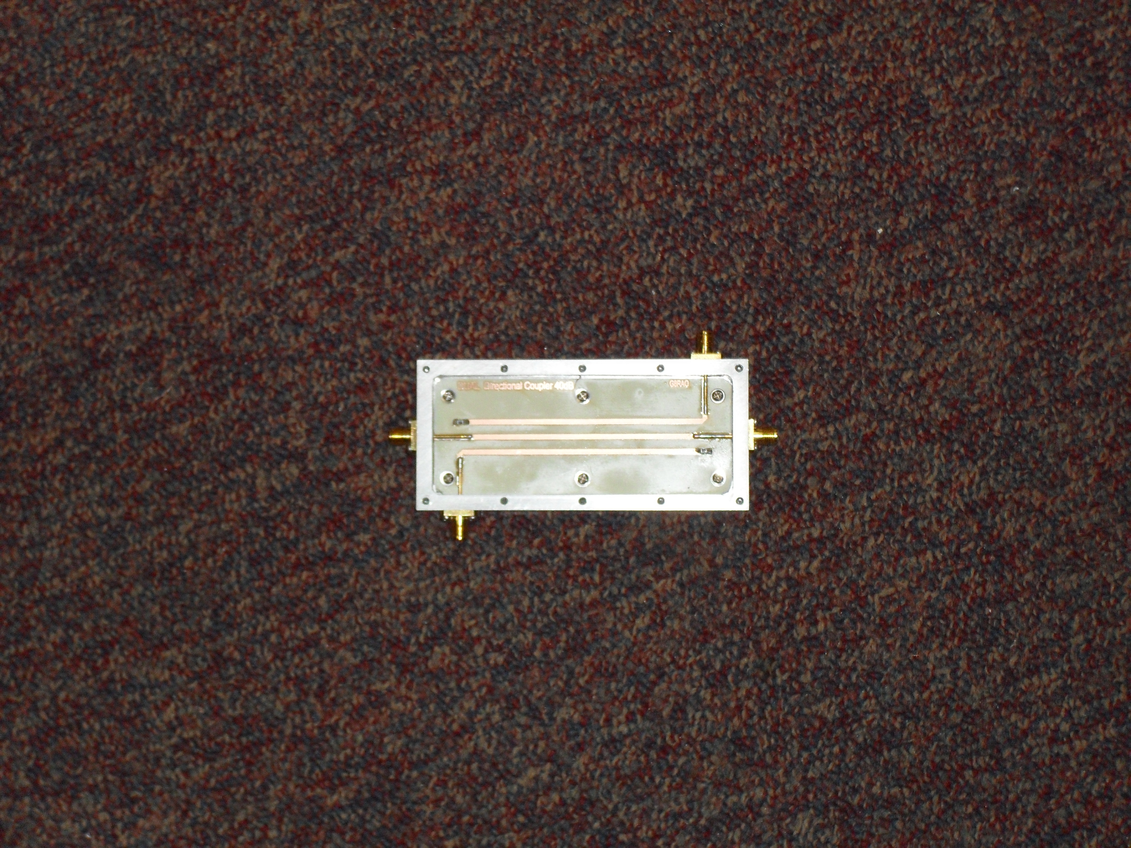
View of the completed 145MHz Dual Coupler
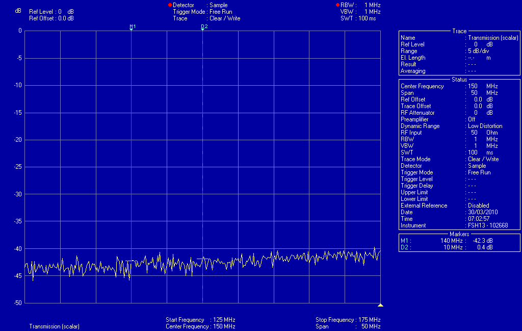
The frequency response of the coupler as plotted using an FSH3 spectrum analyser
The parts listing for ALL coupler variants only one PCB is used per coupler
| Item | Manufacturer | Part No. | Supplier | Supplier's Part No | QTY |
| PCB |
Homemade | 145MHz Dual Coupler | Homemade | To suit band Chosen | 1 |
|
|
Homemade | 435 MHz Dual Coupler | Homemade | To suit band Chosen | 1 |
|
|
Homemade | 1296MHz Dual Coupler | Homemade | To suit band Chosen | 1 |
| Housing |
Homemade | Homemade | 1 | ||
| Cover |
Homemade | Homemade | 1 | ||
| 100R "0805" |
Various |
4 | |||
| SMA Socket |
Various | FEC | 105 - 6376 |
4 | |
| M2.0 x 6 mm " A2" |
Various | FEC |
142 - 0028 | 22 | |
| M2.5 x 6 mm "A2" |
Various | FEC | 142 - 0030 | 12 | |
| M2.0 Crinkle " A2" |
Various | FEC | 161 - 4000 | 6 | |
| FEC is |
Farnell | Electronic Components |
After making these couplers I found their directivity to be poor only about 10 - 12 db , not much use if you are trying to measure return losses greater than15 dB so a redesign in the light of experience will follow shortly these will use STRIPLINE techniques not Microstrip , the reason for the lack of directivity being due to the inherent differential speeds of propagation on the transmission & coupled lines caused by the different dieletric above & below the transmission lines .
Back to Amateur Radio Projects
This page last updated 17/03/2014