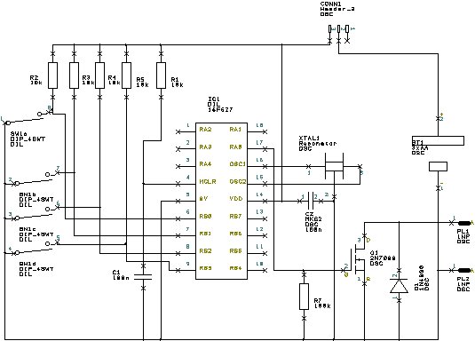
This project was built due to the need to identify transmissions when operating my transmitting equipment during the testing of the Table Top 200 Watt 145MHz Amplifier after it was reported to me by a local radio amateur ( 1/2 mile distant ) that he could hear a signal on the frequencies I had been using , fortunately for me this amateur ( G8MKE ) is my father in law . This meant that even though I was using a non radiating load or the 100 Watt power attenuator there was sufficient leakage from the amplifier with the lid off , the same problem also occured during testing of the low pass filter module .The module consists of a PIC microcontroller driving a small FET to key the transmitter's morse key input , with a four way switch to enable different preprogrammed message to be selected eg alternative callsign ( my XYL is licensed as G0NNF ) or possibly an alternative location eg my works QTH if It test it there .
![]()
The code is a TEXT file ( Keyer_01.asm) and may be edited and saved using Notepad or similar ,remember to rename the file to .ASM after saving it for the assembler program to work .DO NOT use Microsoft WORD or similar as they put formatting characters in which the assembler program ( MPASM ) will reject and then fail to create the hex file Keyer_01.HEX for the PIC!
This page last updated 11/11/2009