This module contains all of the circuitry neccesary to obtain DC voltages which are directly proportional to the forward & reverse power on the amplifier's output cable .
It uses a dual directional coupler made from semi - rigid coax with terminating attenuators to both present an adequate match to the sampling line as well as adjusting the coupled power to be within the middle of the range of the integrated circuit power detectors used.
The sampled RF power is obtained by using a coupler made from two pieces of semi - rigid coax with part of the outer layer removed from both lines ,the outers of both coax cables are soldered together to ensure the screening of the coupled line the main through line is soldered to both the pcb top earth plane and the coax connectors at each end .The coupled power is applied to the attenuators at each end of the coupled line before being applied to the power detector IC's ( Maxim MAX2015 ) ,the attenuator on the opposite end forming the termination for the coupled line to ensure a reasonable level of directivity . Afterall you only want the detector to measure the power on the coupled line in the intended direction ,otherwise this means that the ratio of forward to reverse power will be meaningless so the reverse power limit to protect the active device in the power amplifier would be unable to be set .
The DC outputs from the power detectors are passed through feedthrough capacitors as well as the DC supply for the power detectors in order to minimise the leakage of RF power causing any instability within the amplifier control circuits the power detectors have their own linear regulator on the PCB to minimise any conducted EMC problems .The Coaxial coupler is inserted in the circuit between PL1,2,3&PL4 the main line between PL3 & PL4 the " Coupled line " between PL1 & PL2 .
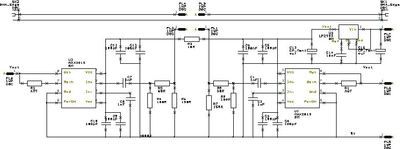
The schematic drawing of the RF sampling module all parts are surface mount .
PCB artwork to be inserted here
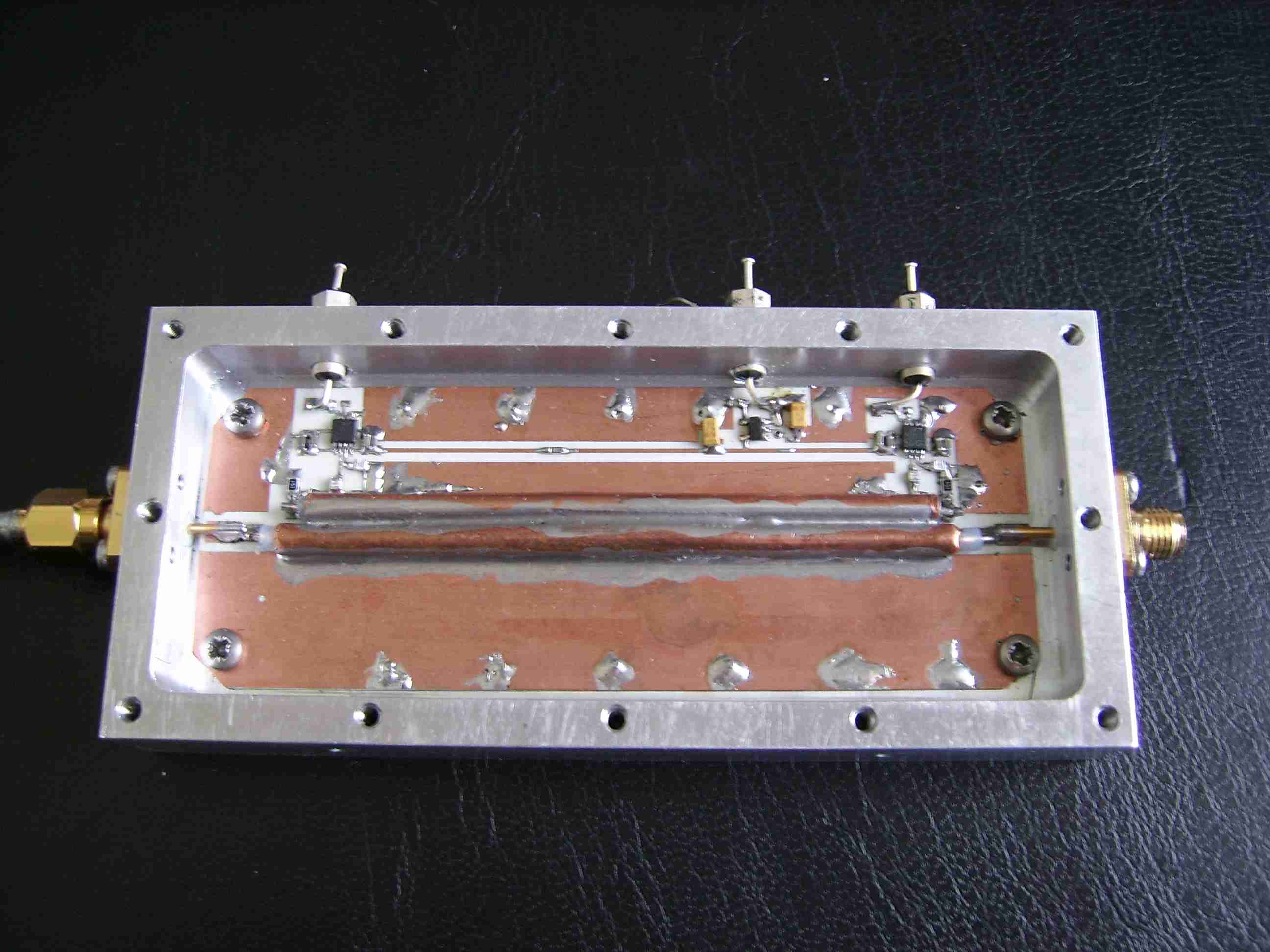
The completed RF sampling Module below
Testing of the Output Power Monitor
The unit was tested for " S11 " ( Reverse power )& " S21" ( Forward Power ) to ensure that it would not cause any problems when inserted into the output from the amplifier. The unit was then tested initially at about 10 watts as was the case for the filter measuring the output sensor values for both forward & reflected power with a matched load then a calibrated mismatch was applied to test the actual values of the power sensors ( allowing both for coupling coefficient , directivity & linearity ) of the line coupler & sensor integrated circuits this means that the ratio at full power should also be the same this means that testing with the known mismatch is much safer . The mismatch was made using an attenuator of half the required return loss terminated in a short circuit similar in construction to the input attenuator .
After using the amplifier for a short period of time during testing it was found that the coupler lacked sufficient directivity and it had been replaced with a dual directional coupler & seperate detector heads which will be detailed soon .