A Versatile bias supply
for Depletion Mode
GaAs & GaN Power
Amplifiers
This
project was inspired by research activities of several students who were using
multiple power supplies to run some experimental power amplifiers using the
modern Gallium Nitride power FETs , these depletion mode devices require the
correct sequencing of the supplies , unfortunately the loss of the gate bias
with ALL devices both GaN & the earlier GaAs models results in catasrophic
failure ( Murphy's law stating the more expensive the device the quicker it's
demise ! ) So with the prospect of the surplus devices being made available for
my Amateur radio activities an " Integrated & Interlocked supply
module " was developed. As both 12V & 28 V Fet's were to become
available it was decided to make one unit to cover all options. There were
already similar ideas on the Kuhne Electronics website (run by DB6NT ) for use
in some of his designs using several IC's .
The
heart of the circuit is the Linear Technology LTC1261 charge pump &
regulator ,basically this takes in 3 - 6 volts positive to generate a negative
voltage which is then regulated internally (but may be set externally in some
of the variants ) the regulated voltage is applied to an internal comparator
which can be used to switch on the Fet's drain supply sequentially ( via a
suitable switch )

Circuit for the versatile bias regulator
From the
circuit above it can be seen that a simple level translator has been used with
a " P Channel " power mosfet to switch the Drain supply on . This is
due to the LTC1261 being limited to 16 v max on the " Power good "
output , it is fed from a 7805 type regulator to ensure it can be used on the
28V supply option , the whole design was made " Surface mount " on a
single sided PCB , there is no reason however not to incorporate this on to the
RF amplifier's PCB for a more compact unit if should you wish to.
Component overlay of the completed PCB , the finished size is
40 mm x 30 mm
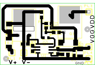
Component overlay of completed PCB
To make the PCB using
the contact print technique requires the use of a "
Mirrored " artwork for the top copper layer
link to PDF of mirrored artwork

Picture of the protoype PCB in use on a 20
Watt amplifier for 3.4 GHz " Wimax band
"( This mean's that the student's Don't blow up the devices before I get my chance
to " Salvage " them ).
The testing procedure is to use a small pot (to temporarily
replace R6 ) to set the bias point of the regulator according to the desired
mode of operation ( Class AB or Class C ) as derived from the manufacturer's
data sheet . This pot is then replaced with the nearest preferred value fixed
resistor(s) and the board is ready for use .
Item
|
Manufacturer |
Part Number |
Supplier |
Suppliers part No |
QTY |
| PCB |
Home made |
|
Home made |
|
1 |
| LTC1261 |
Linear Technology |
LTC1261CS8 |
FEC |
127 - 3847 |
1 |
| 78M05 |
Various |
|
FEC |
170 - 3354 |
1 |
| 1K "0805 " |
Various |
|
Various |
|
1 |
| 4K7 " 0805 " |
Various |
|
Various |
|
1 |
| 10K " 0805 " |
Various |
|
Various |
|
1 |
| 12K " 0805 " |
Various |
|
Various |
|
1 |
| 47K " 0805 " |
Various |
|
Various |
|
1 |
| 100nF " 0805 " |
Various |
|
Various |
|
3 |
| 1uf Tant 35V |
Kemet |
T491B105K035AT |
FEC |
145 - 7432 |
2 |
| BC846 |
Various |
BC846 |
FEC |
179 - 8072 |
1 |
| IRFR5305S |
International Rectifier |
IRFR5305SPBF |
FEC |
864 - 9820 |
1 |
| BZV55C15 |
Various |
|
FEC |
109 - 7187 |
1 |
| 1A5 fuse ( PTC ) |
Polyfuse |
1812L110/33MR |
FEC |
182 - 2213 |
1 |
| Alternative for IRFR5305 |
ST Microelectronics |
SUD50P04-08-GE3 |
FEC |
179 - 4811 |
1 |
| |
|
|
|
|
|
This project has since become the " standard "
bias circuit used by both undergraduate & post graduate students for
further work using GaN Fets .
With some of the more modern higher power fets which
require less than 1v25 ( the regulator's minimum output with the feedback pin
effectively grounded ) there is an amendment to take this feedback resistor to
the regulated positive supply as suggested in the manufacturer's data sheet ,
this is currently easily done by using a small wire ended resistor ( a revised
artwork will appear soon ).
Back to Amateur Radio
Projects
This page was last updated10th Aug
2011