What Not to Do !
This page shows you what not to do when
dealing with circuits at Radio Frequencies, I have illustrated it from various
Student's projects that went wrong .
For convenience we will take Radio Frequencies to mean
any circuit working above about 50kHz
If you are using 433MHz Wireless modules for a digital
link DO NOT even consider using
either Veroboard or a Solderless breadboard USE a Printed Circuit
Board . Why ? Because the basic construction of a solderless breadboard
is a bank of capacitors of around 10 - 20 pF this capacitor has a shunt
reactance of < 50R so effectively causing the RF power to be lost and not
available to the aerial .
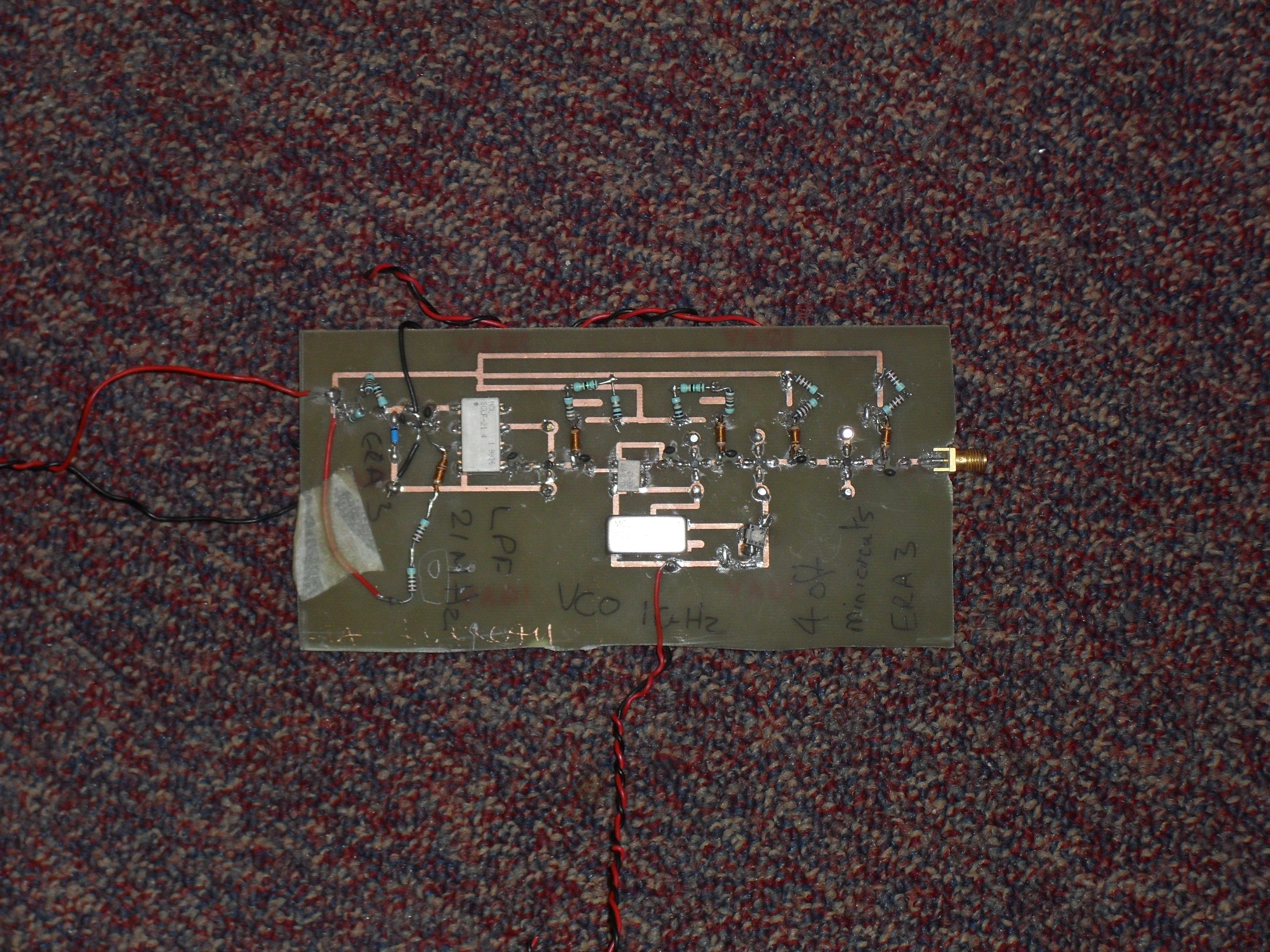
This item is a student's 1GHz radio transmitter .

This project has several problems , due to the choice of
components requiring a mixture of through hole & surface mount techniques .
If you study the photograph you will notice firstly the total lack of any
decoupling capacitors on the supply rails . The MMIC amplifiers are soldered
correctly to the board as intended for the frequency of operation BUT
the tracks connecting them are not 50 R microstripline so there is an impedance
mismatch present , then we have the DC blocking capacitors between the stages
these are wire leaded types with 5mm long leads ( that's an inductor at 1GHz ),
this together with the 10mm long earth tracks from the MMIC's to the veropins
which eventually connect to the groundplane , these will also reduce the gain
together with the risk of instability occuring given the bandwidth of the
MMIC's chosen ( DC - 6GHz ). The Voltage Controlled
Oscillator ( Silver box with 8 legs )is a through hole device it is
mounted above the PCB on it's connecting pins , note there is no voltage
regulator or decoupling of the supplies or tuning voltage are present . The
output of the mixer should be 50R microstripline to the mixer , the earth
connection from the VCO is nearly 20 mm long, the same long earth path for the
mixer module also occurs .The inductors in the supply to the MMIC's have 3 mm
long leads so that they are not the intended value and also can lead to
instability by acting as an Aerial given the high gain for the three cascaded
amplifiers this is also brought about by the use of conventional wire ended
resistors used to set the supply of the MMIC's allowing for radiated signal to
be coupled from stage to stage . The power supply leads for ALL the various
modules all behave as Aerials so that unless the student is testing the project
in an EMC or Anechoic chamber it will amplify the local Wlan in the lab , the
local Cellphone transmitters ( Both handset & Base station ) picked up on
the leads due to the lack of decoupling components !
This project is a cascaded Wilkinson splitter / combiner
for 2.4GHz
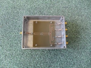
As can be seen the student has cased up the PCB in a
small diecast metal box but due to the way that they have added the earthing (
using lengths of thin wire , just think of the Inductance at this frequency !)
for the semi - rigid coax to the boards they have negated some of the benefits
of using the coax , a better solution would to be have used coaxial edge
transitions ( using bulkhead types as required ) and plug & socket
extension lead (s) to allow for the fact that the diecast box walls are not
parallel to each other this would then maintain system impedance for all the RF
paths and provide correct earthing but the transmission lines may have to be
extended to ensure that the edge transitions do not short out the folded lines
for ports in the middle , again this can be solved at the modelling stage prior
to producing the PCB .
This page will be added to
as & when students request help on a particular subject
Back to RF Design For Students
This page last updated 9th May 2011