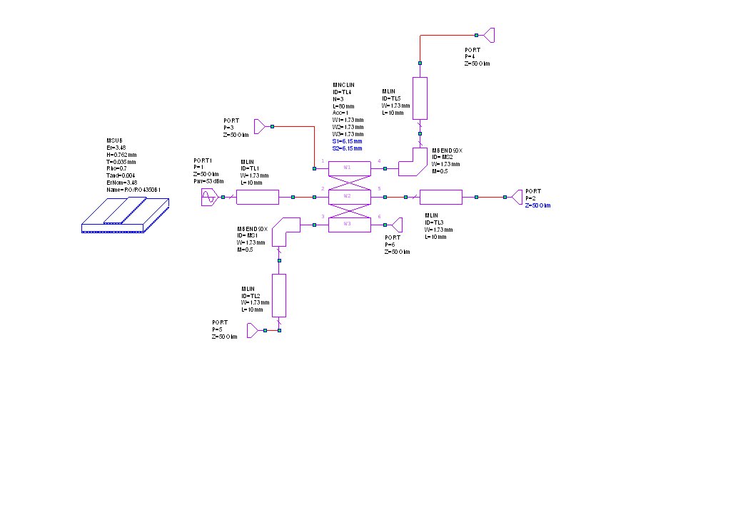
When testing the operation of the dual directional coupler (Link) I needed to be able to put known loads ( Other than of System impedance ) on to the output so although the commercial SMA termination was able to prove the directivity ( <35dB ) checked by using a VNA ( HP8722D ) , so with recourse to my favourite modelling software (MicroWave Office ) I was able to design using standard parts a range of known mismatches which were put on to the output of the coupler and the Return Loss measured , they were also checked on a VNA to prove their value, the nominal design values were chosen from the simple expediency of what was available . The values of 10dB RL , 14 dB RL and 20dB RL using the resistors S parameters from the website , This only has the 0603 parts but if you want to download the S2P files from the manufacturers website other values can be designed , this does limit the power dissipation to +23 dBm ,there is no problem using 0805 or 1206 parts to raise power rating of the mismatch to +27dBm ( 1/2 Watt ) , but the larger parts will reduce the upper frequency limit of the mismatch , the target maximum frequency being at least 1.5GHz to enable testing on the 2m , 70cm & 23cm Amateur radio bands.
MWO cct
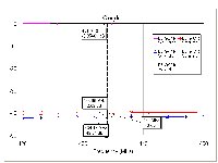
Modelled Return Loss
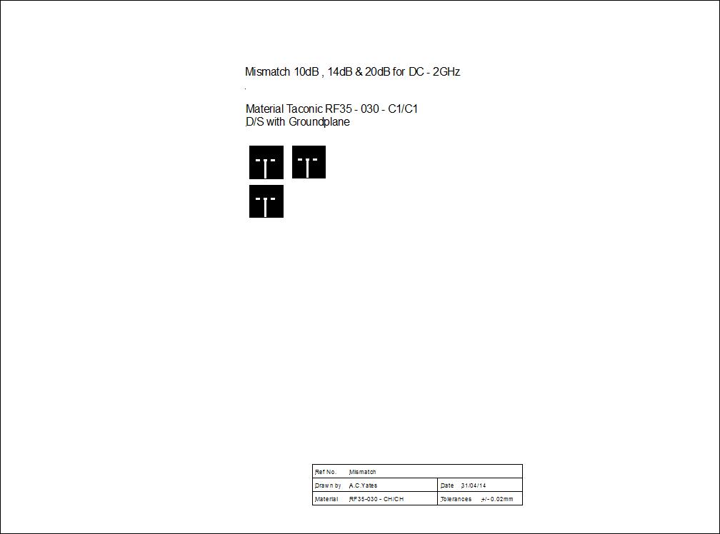
Cad Artwork PDF
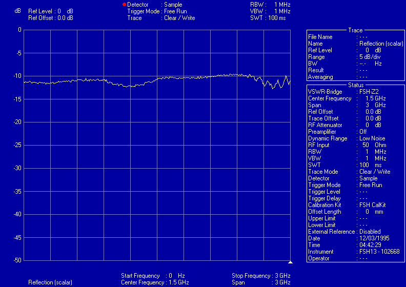
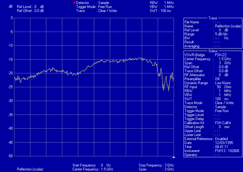
Screen Capture of Return loss 10dB
Screen Capture of Return loss 14dB
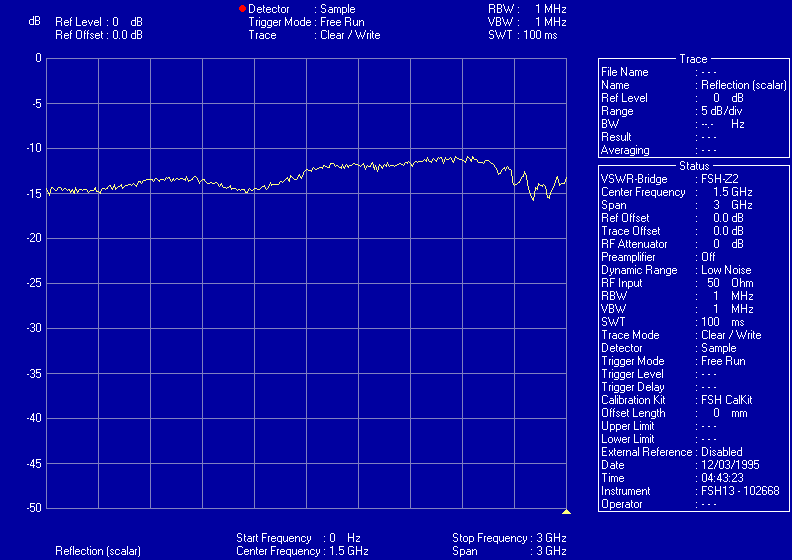
Screen Capture of Return loss 20dB
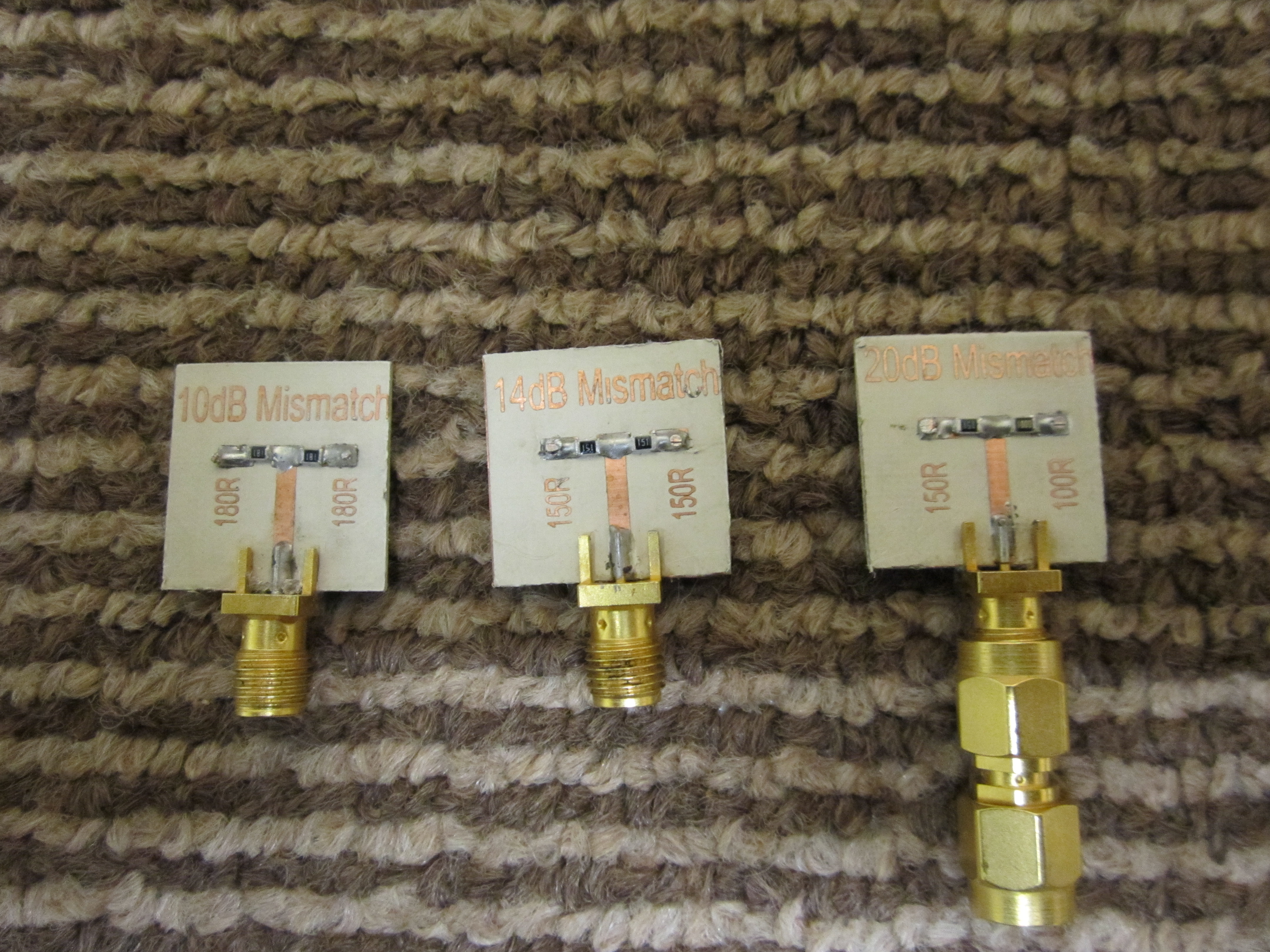
Completed Mismatch Loads
This page last updated 15/01/15