A 100 watt Power Attenuator for up
to 2.5GHz
The testing of power transmitting
equipment requires some form of load to absorb the RF power generated in the
equipment , there are two types of load radiating & non radiating . The
Aerial is the normally " Radiating " load used, however if you wish
to measure the power safely without causing interference to other users a
" Non Radiating load " often called a " Dummy load " is
used.In order to measure the power out and any spurious signals I could have
used an " Inline " power meter and a sampling line ( Directional
Coupler ) to couple the transmitted signal into a spectrum analyser ,however
this means that the " sampled " signal would have different values of
coupling at different frequencies making the measurement of harmonics etc more
difficult so the use of a power attenuator with a " Flat " frequency
response means that " ALL " signals will be applied to the test gear
( Analyser or mW power meter ) will be reduced by the same amount eg A 30dB
attenuation value turning the 200 Watts of the amplifier in to 200mW which is
just about the limit of most spectrum analysers ( an additional 10dB would have
been preferred for safety for the test gear ) but this can be added by using a
standard 2 watt commercial attenuator or by making a similar value home made
attenuator using standard SMD parts and a pcb ( I feel another project coming
up ? ) See the Dual MMIC amp for suitable
attenuators , I said a project would occur .
So after the usual web search , I found a couple of
suppliers ( Anaren &
Aeroflex )
of 100 Watt continuous rated power attenuator chips which were pulse rated at a
higher value , so I set out to design & build a continuously rated
attenuator using standard heatsinks and a " Milled " housing to take
the attenuator and it's PCB . The PCB was modelled using " Microwave
Office " and designed to take the attenuator chip in a cutout. The
response of the real attenuator closely following the modelled values .
The PCB used Rogers RT5880 - 062 - C1/C1 to minimise the
losses up to the designed maximum operating frequency .DO NOT be tempted to redesign the
PCB to use FR4 because above 1GHz especially at High Power it can catch fire
after continuous use due to it's dielectric losses .
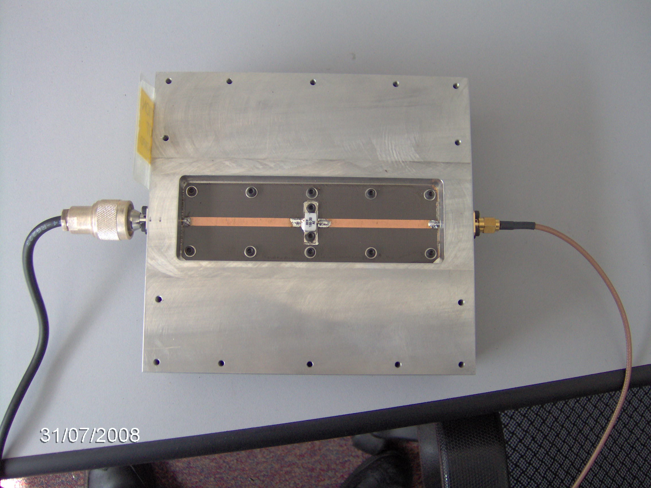
The pictures below show the assembled attenuator and also
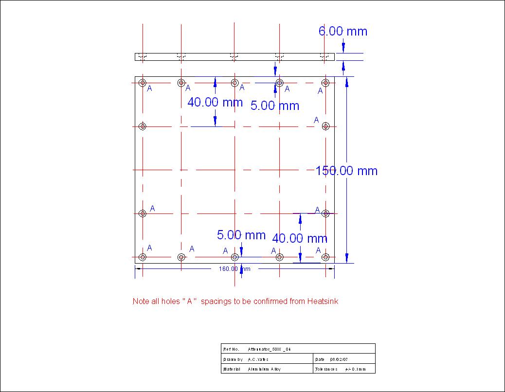
it's internal construction ,note the use of multiple screws along the PCB is to
minimise any stray reasonances caused by the PCB's groundplane only contacting
the housing at the corners .The connectors used are " N" type and SMA
flanged both with the same fixing centers so that either type could be used (
the SMA can take upto 500 W according to the manufacturer ! )
View of the attenuator chip & PCB in the milled
housing

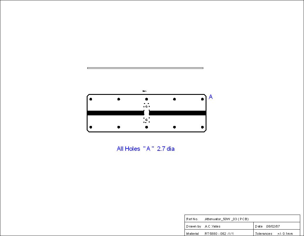
The holes for the securing the PCB and the power
attenuator " Chip " are all the same size ( to minimise the chance of
damaging the attenuator chip as the insulating layer in the device is "
Beryllium Oxide " ) so the choice of M2.5 " Allen " headed
screws meant that the attenuator chip could be " Torqued " down as
per the manufacturer's instructions as well as using them on the connectors .
The heatsinks were also secured to the milled housing using " Allen "
headed screws to enable adequate torque to be applied to hold the heatsinks
flat after they had been " skimmed " on a milling machine to ensure a
metal to metal join again to minimise any stray resonances they naturally will
bend due to the stress of the extrusion process used to make them . The design information for choosing the
heatsinks came from ( Link) this
enabled me to check the various suppliers for the relevant heatsinks and
subesquently buy them , a mistake by the supplier ended up with me having two
sets of heatsinks so I made a duplicate attenuator for " work " with
a pair of SMA connectors on it .This was used in testing some student's 3.4 GHz
WiMax amplifiers .( Note since this project was made a safer form of power
attenuator chip using Aluminium Nitride as the insulator has become available
from Anaren )
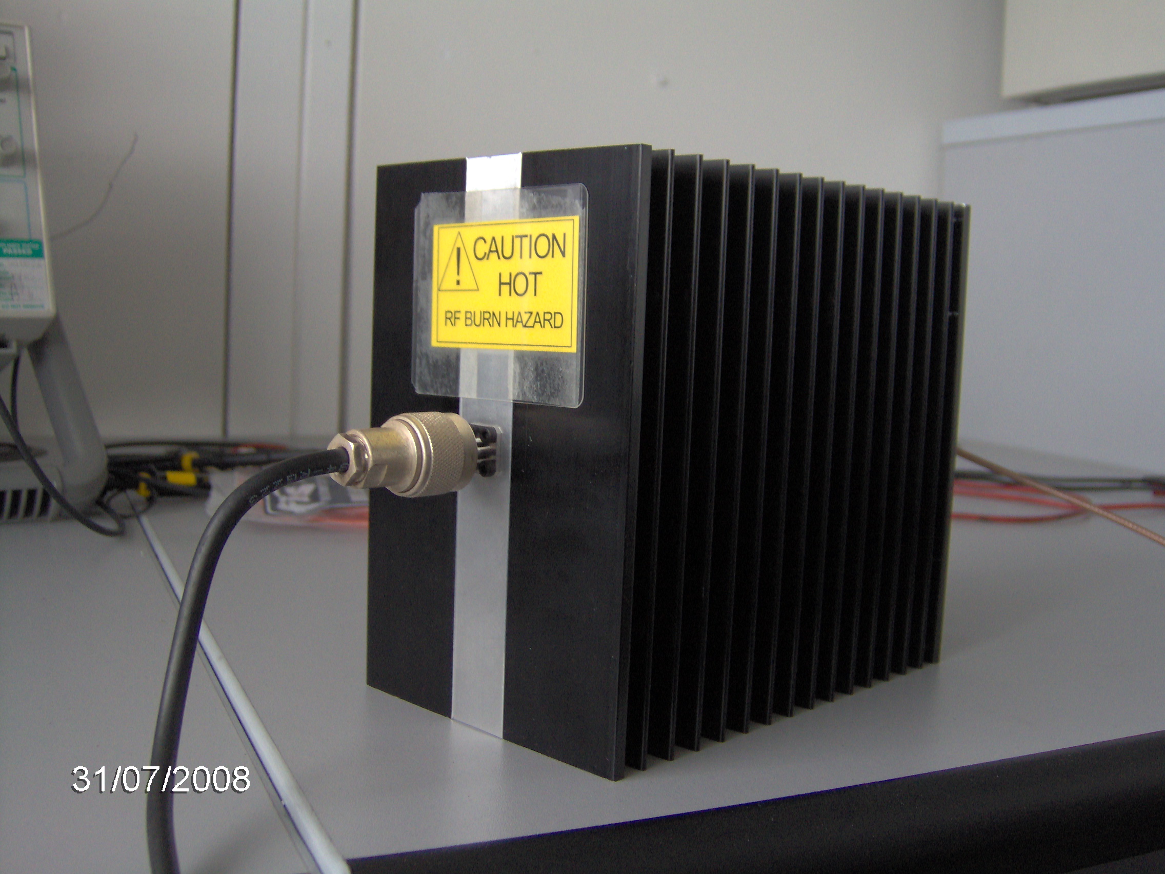
View of the completed attenuator in use testing my table
top amplifier in the laboratory at work, note the " Homemade " Safety
label to warn people of it's immediate Hazards!

Here are the responses for the attenuator taken at spot
frequencies using the Rhode & Schwarz FSH3 using the internal marker , they
were also checked using a signal generator & power meter hot & cold to
confirm the performance the value beneath the images was taken using a Marconi
2022 & an HP435 Power meter with the attenuator heated using an external
heater ( 2kW fan heater ) to 75deg C case temperature showing only minor
variations from the swept result values .

70MHz attenuation 29.97dB

145MHz attenuation 30.07dB

435MHz attenuation 30.05dB

1260 MHz attenuation 30.12dB
Parts listing for the Attenuator
Item
|
Manufacturer
|
Part Number
|
Supplier
|
Suppliers part No
|
QTY
|
Attenuator
|
Anaren
|
RFP100 - 30AE
|
Anaren
|
RFP100 - 30AE
|
1
|
M2.5 x 6 mm
|
Various
|
- |
FEC
|
883 - 5497
|
20
|
M3.0 x 16 mm
|
Various
|
- |
FEC
|
883 - 5560
|
28
|
M3 washer
|
Various
|
- |
FEC
|
161 - 4001
|
28
|
SMA socket
|
Huber & Suhner
|
23-SMA-50-0-3/111_NE
|
FEC
|
105 - 6376
|
1
|
N socket
|
Huber & Suhner
|
23-N-50-0-30/133_NE
|
FC Lane
|
23-N-50-0-30/133_NE
|
1
|
Heatsink
|
Marston
|
938SP
|
FEC
|
526 - 794
|
2
|
Aluminium bar
|
170 x 170 x
46 mm
|
- |
Various
|
|
1
|
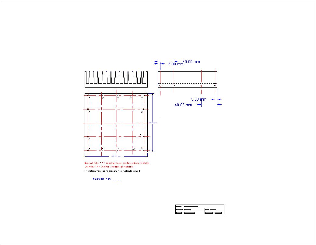
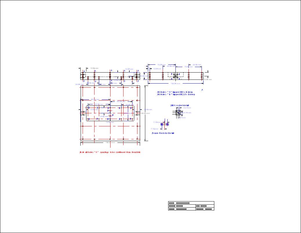
The CAD drawings of the attenuator PCB , housing &
heatsink are all available as PDF' below
The printer ready PDF's for the drawings
General assembly drawing

Heatsink drawing
Module Housing
Printed Circuit board
A 50 Watt version using one heatsink has also been
constructed for a fellow radio amateur see below for the drawings
The printer ready PDF's for the drawings
General Assembly

Heatsink drawing
Module Housing
Printed Circuit board
Housing Cover
As an after thought I decided to see what was on the
commercial market and found similar designs were available from
Bird
Rf Products and several other manufacturers although the physical size was
the same , although the styling was a little different .
Back to Amateur Radio Projects
This page last updated 04 May 2018