Basic Metrology ( Measuring Techniques)
This is to show how the type(s) of measurement equipment
to be used when measuring the parameters of your circuit , it depends not just
on what you wish to measure but also on the magnitudes of these signals to be
measured.
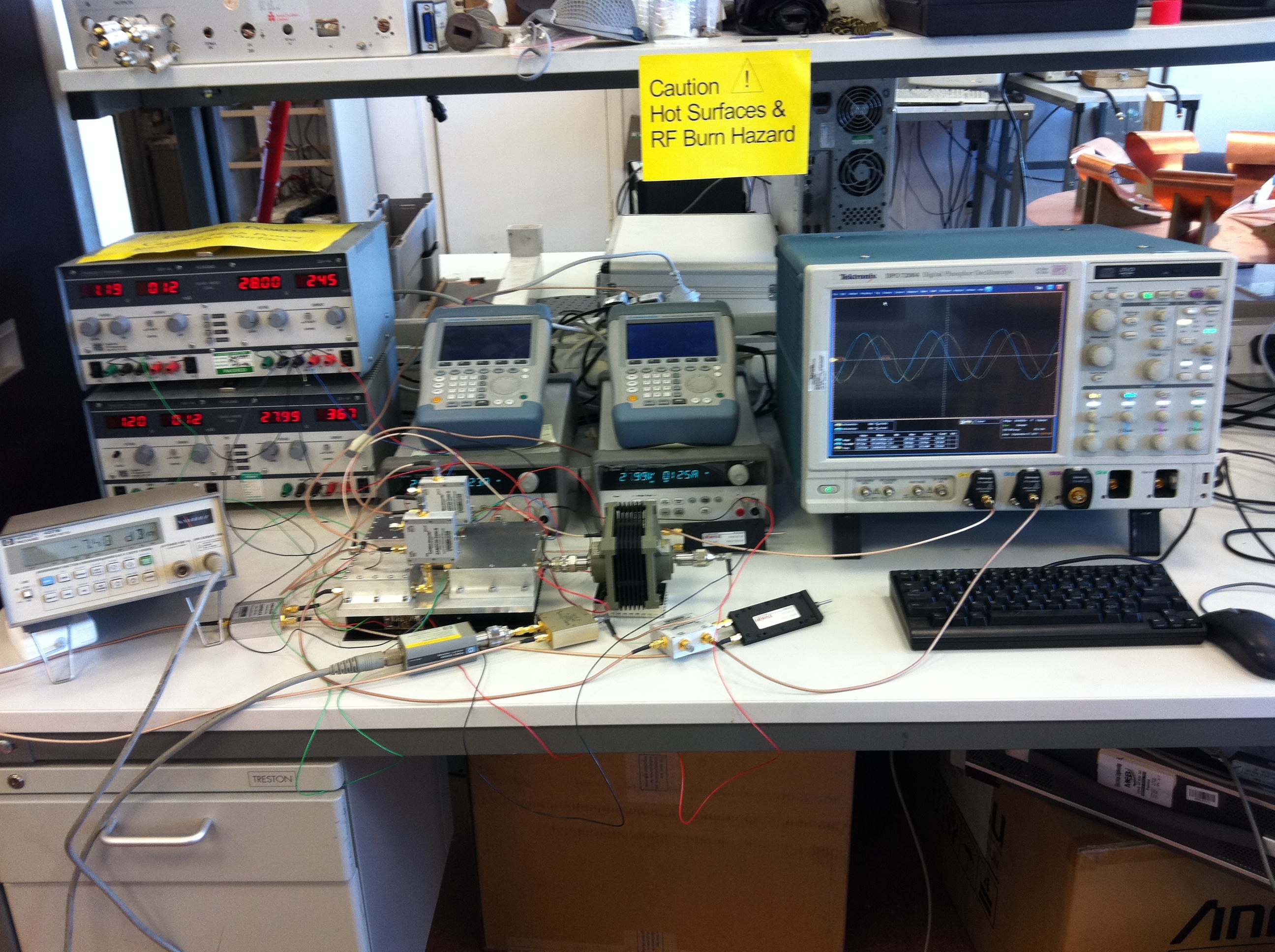
The picture below shows a range of measurement devices
combined to measure a 20 watt power amplifier for 3.4 GHz , most measurements
for the basic S11 ,S22 ,S21 & S12 can be done using a Vector Network Analyser ( or a Spectrum Analyser with it's
own Tracking Generator & Return
Loss Bridge )
provided the circuit under test is either passive or it's output is less than
10mW ( +10dBm ) with NO DC present on the
connections to it .

To measure at any
greater power will require the use of attenuators or directional couplers to
bring the magnitude(s) of the signals into the range of the test equipment ,
this also leads to making errors by the wrong choice of techniques .For
instance you cannot simply add an attenuator to the input of a VNA to measure
the S22 of an amplifier capable of more than +10dBm O/P , because the VNA will
effectively only see twice the value of the attenuator and not the real value
of the stage under test . eg for a VNA
limited to +10dBm input measuring the output of a 30dBm amplifier you will
need at least 20dB of attenuation , so from 1st principles the port connected
to the attenuator will see a return loss of 2 x 20dB ( Assuming the attenuator
is a good quality item ) with either O/C or S/C applied to it . The only way
that you can measure these magnitudes of power is INDIRECTLY using a directional coupler and a
termination of system impedance & suitable power rating , then comparing
the incident and reflected power to obtain the Return Loss (
Match ) the same technique can also be used to measure input match for a power
amplifier when driven at correct ( Large ) signal levels rather than the usual
0 to + 10dBm ( Small ) output from the VNA , this technique also allows the
phase delay of the circuit to be measured at the desired power level not just
at small signal values ( But it's always a good idea to test at lower power
levels first ! ) The test setup above shows the main 20 watt amplifier (
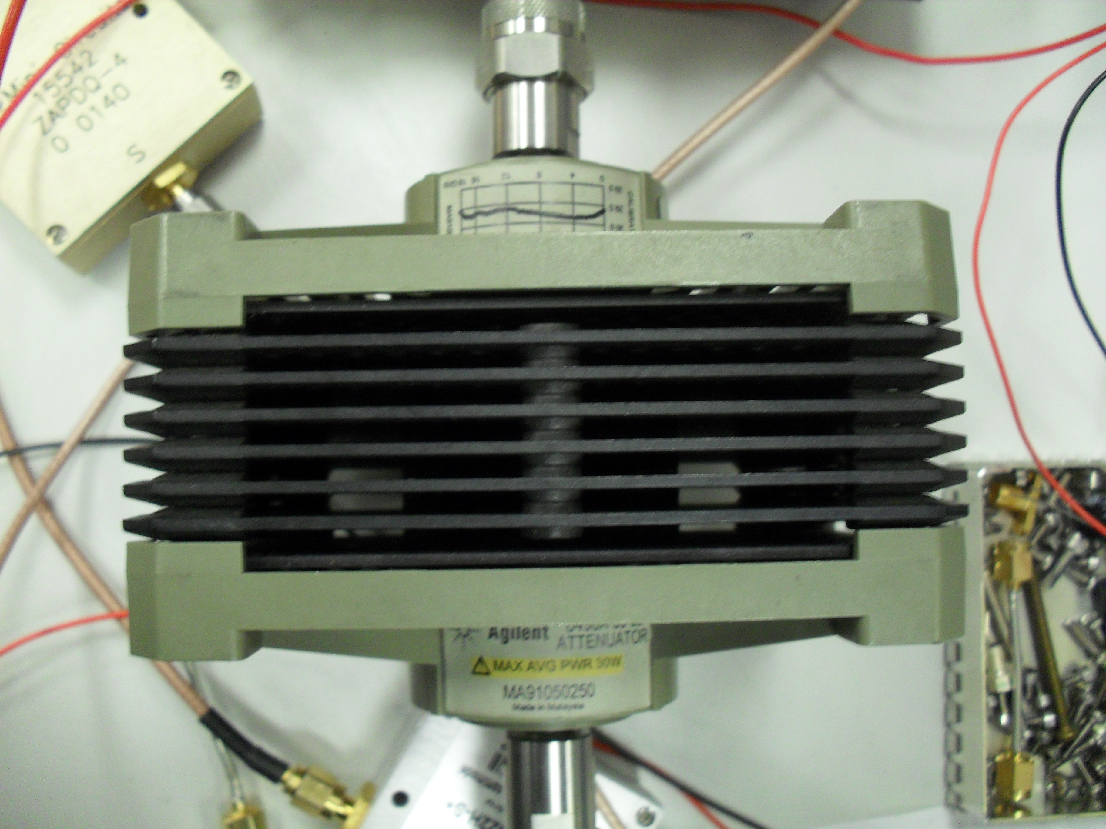
Working at 3.4 GHz ) fed into a precision power attenuator capable of 30 Watts
continuous dissipation with a frequency vs attenuation graph showing it's
performance ( DC - 12GHz ) the output from the power attenuator is fed to a
splitter to enable the power to be measured on a power meter , along with the
spectrum analyser ( off screen ) to measure the output spectrum ( harmonics etc
). The input power & return loss for the power amplifier is measured using
a pair of directional couplers one for each channel , again the power is
measured , this time using a pair of Spectrum Analysers to ensure
the signals from the driver amplifiers are " clean " so that any
spurious signals seen on the output must be generated in the high power
amplifier section . The signals supplied to the driver amplifiers are capable
of being adjusted in phase using a pair of adjustable transmission line phase
shifters ( two are required to get the correct range ) again these signals are
sampled and fed to the large Digital Storage Oscilloscope
, this is used to measure the phase angle between the two signals applied to
the driver stages . When measuring power it is essential to measure all the
components used , each cable will have an insertion loss , each connector pair
will have a loss ( small but measurable ) and most importantly when dealing
with high power measurements using attenuators is to measure the attenuator at
it's operating temperature ( Yes it does vary ,often upto 0.5db , that's an
error of 10%) so if you are for example making efficiency measurements ( DC +
RF in to RF Out ) be warned ! The failure to correctly tighten up the
connectors to the specified torque can also lead to intermittent fluctuations
in power being measured , so the use of the correct torque is neccesary . The
use of a " Breakover " spanner with SMA connectors ( and other
precision connectors ) ensures this value without damaging the connector thread
& nut which can so easily happen with ordinary spanners
( DO NOT USE a 250mm
Adjustable spanner on an SMA !) Yes I've seen
students doing this rather than ask for the correct spanner
.
This leads
to ensuring that ALL the test equipment to be used is not only CALIBRATED to a
known standard ( Certified & traceable ) but that it is also powered up to
reach it's normal operating point ( Typically 1 hour from switch on is
specified by the manufacturer )
Pictures of typical Test Instruments used
in the measurements described on this page

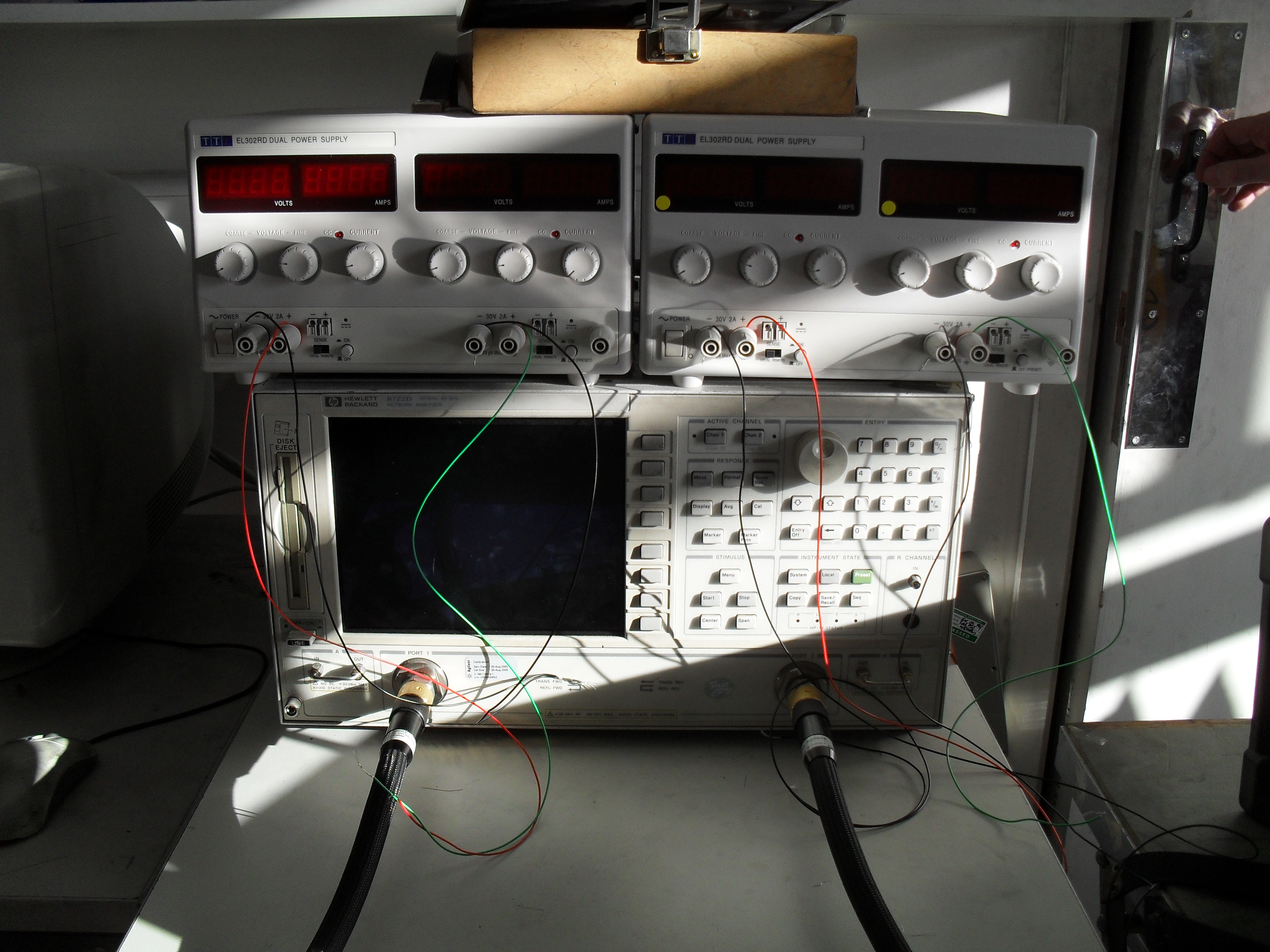
Vector Network Analyser

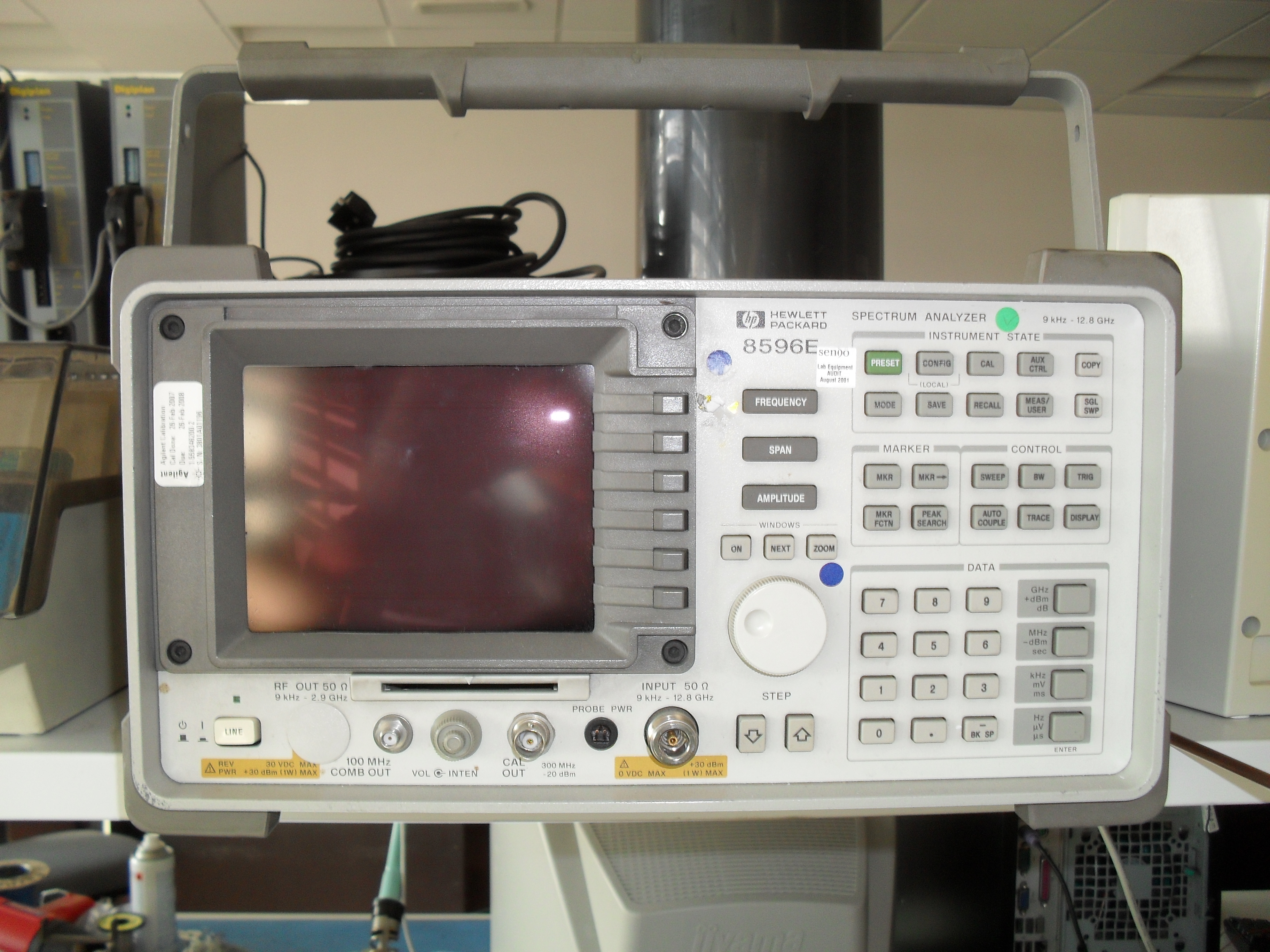
Spectrum Analyser ( Note NO Tracking
generator fitted )

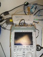
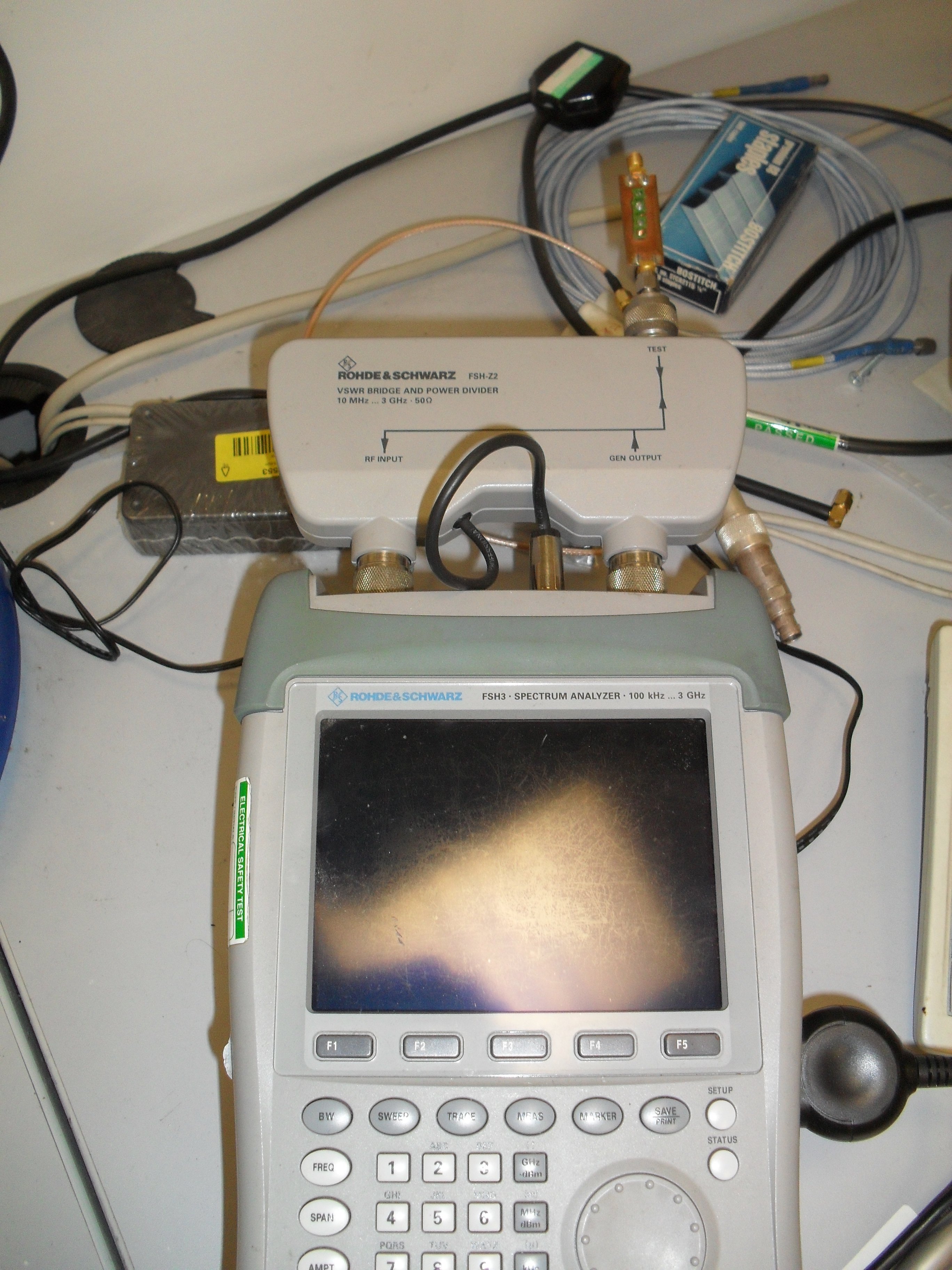
Portable Spectrum Analyser with Tracking Generator
& Return Loss Bridge

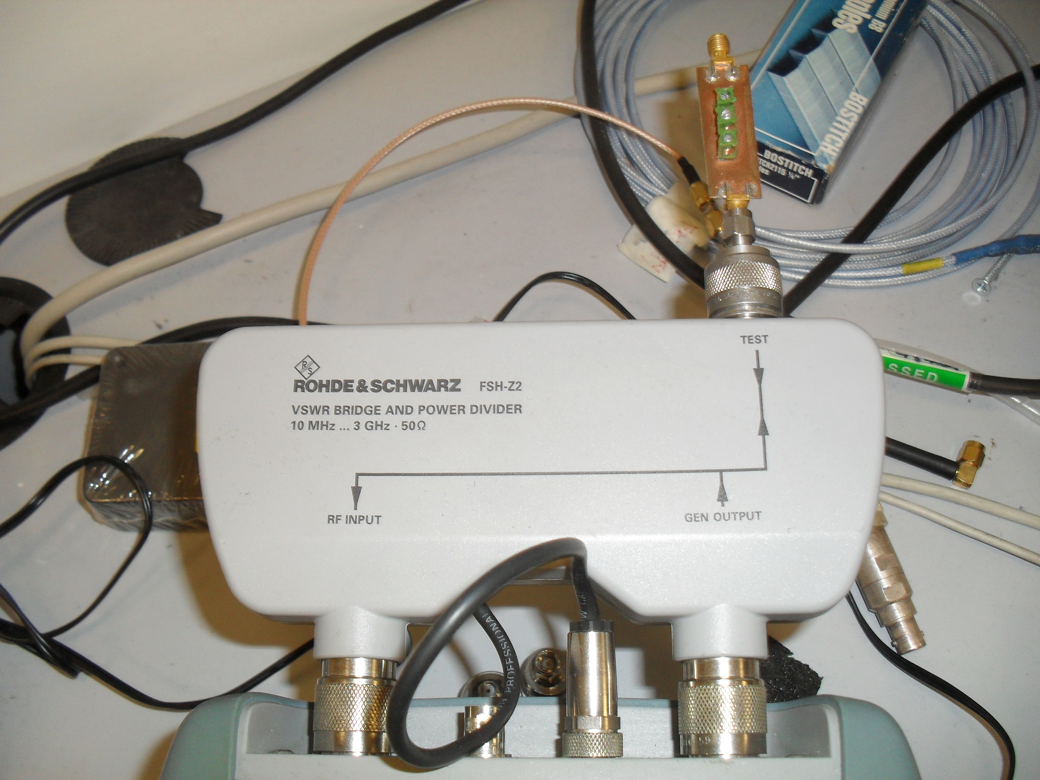
Return Loss Bridge

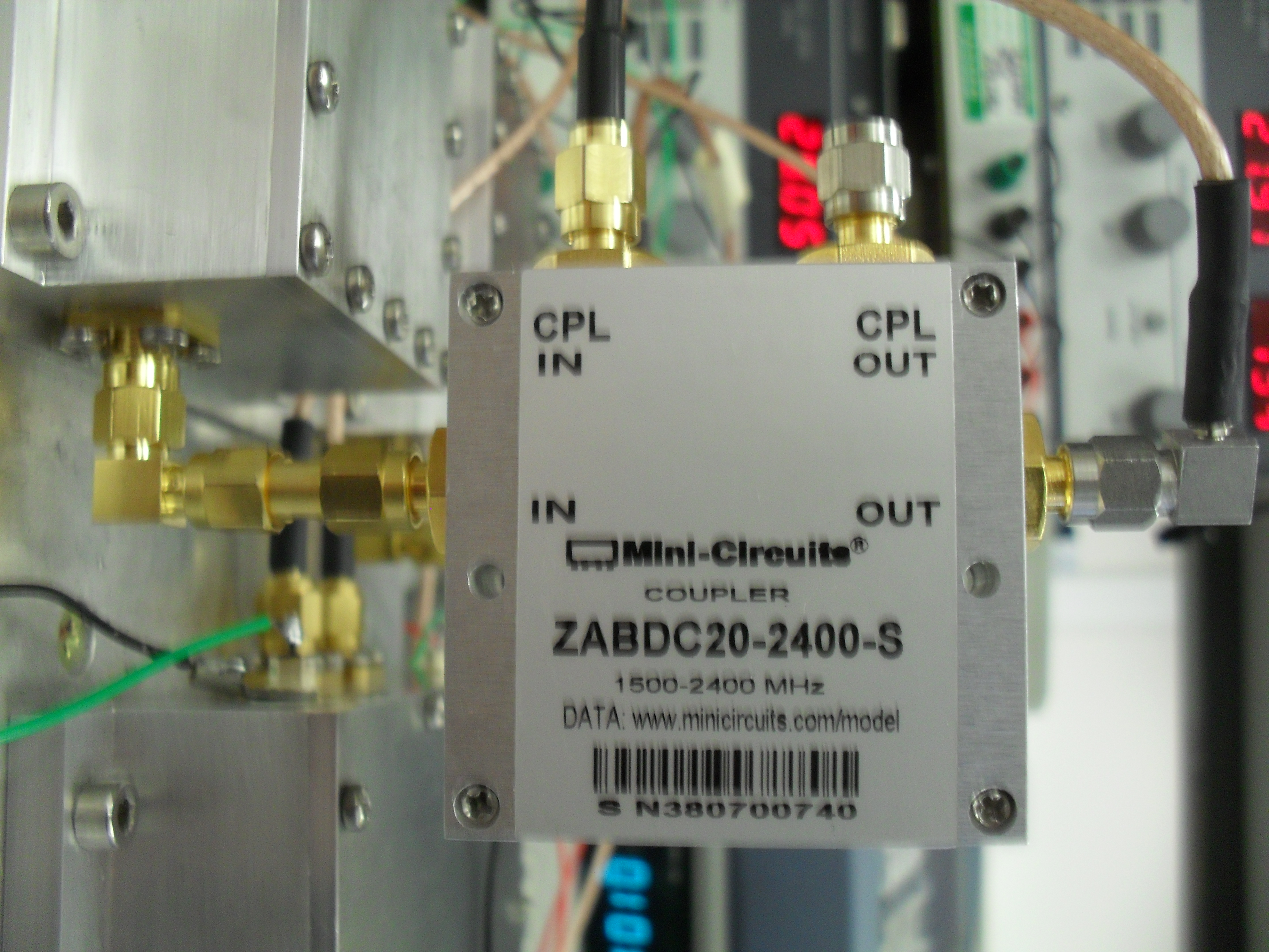
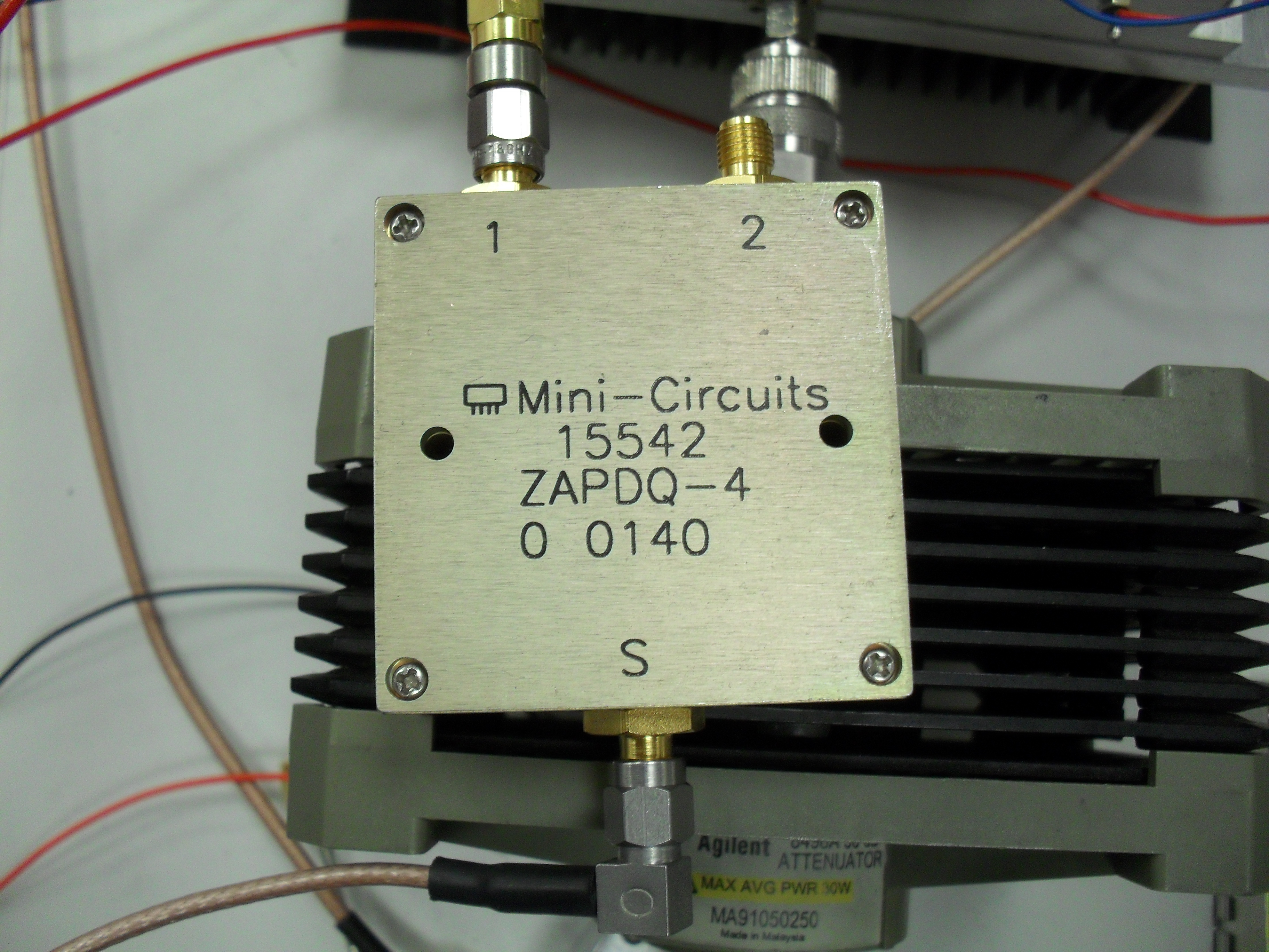
The Directional Coupler used to
sample the RF power from between the driver amplifier & the power amplifier
.

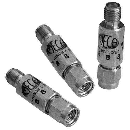
Typical Low power Attenuators 1 or 2 Watt
in SMA connectors
The Power Attenuator used to dissipate the
output from the amplifier under test and reduce the signal amplitude to a level
that the Spectrum Analyser can handle if it is inconvenient to connect the
items under test straight to the measuring port of the instrument then a useful
tip is to use ODD ELECTRICAL 1/2 wave length leads to minimise any reflections
due to discontinuities in cables & connectors etc.
A simple LC Band pass filter being tested for S11
An Alternative instrument for measuring the reponse
Insert Picture of Passive Circuit
under Test here ( 145MHz BPF & HP VNA )
Insert Screen shot of trace
here
A simple LC Band pass filter being tested for S21
Insert Picture of Passive Circuit
under Test here ( 145MHz BPF & FSH3 & RL Bridge )
Insert Picture of Passive Circuit
under Test here ( 145MHz BPF & HP VNA )
Insert Screen shot of trace
here
A
simple transistor amplifier using a single GasFet (
Link to project ) can be
measured using either the VNA or a Spectrum Analyser with a tracking generator
,however , in order to avoid saturating the amplifier when measuring the S21 it
is advisable to turn the O/P of the tracking generator ( VNA port 1) down or
reduce it using a fixed attenuator of 10dB ( nominal value ) on the input to
the amplifier .The use of a signal generator and RF milliwatt meter can enable
the user to test at a single frequency for the gain and get a better idea of
the S21 with respect to stage gain & saturation point ( P1dB ) where the
forward gain falls off due to saturation of the device not readily accomplished
using a swept system such as the VNA with it's limited range to set output
amplitude .
When
measuring the harmonics of an amplifier this can be done in more than one way
either using the Spectrum Analyser with a suitable attenuator on it's input or
by using a directional coupler and termination , there are limits to both ways
!
With
the power attenuator , the frequency response of the attenuator is reasonably
flat across the range of the harmonics to be investigated ( +/- .5dB is quite
typical ) the coupler however will definitely NOT have a flat frequency
response ,however by measuring the coupling coefficent at these respective
frequencies an accurate measurement can be made ( often at higher powers than
an attenuator is capable of ) note the insertion loss of the connecting cables
will also change across the range so these too must be checked if the power out
from the coupler still exceeds the input rating of the Spectrum Analyser then
the use of a low power (1 or 2W rated ) attenuator will be neccesary ( note
this also improves the directionality of the coupler when using a flexible
cable ) another point to remember when using a high power attenuator is the
actual value of attenuation varies with temperature so it is advisable to check
the actual value having warmed it up to the operating temperature there may be
upto 1dB error in the quoted value of attenuation ( that's an error of 20% ) .
This page will be added to shortly when time permits
Back
to Homepage
This page last updated 11/05/2011 6