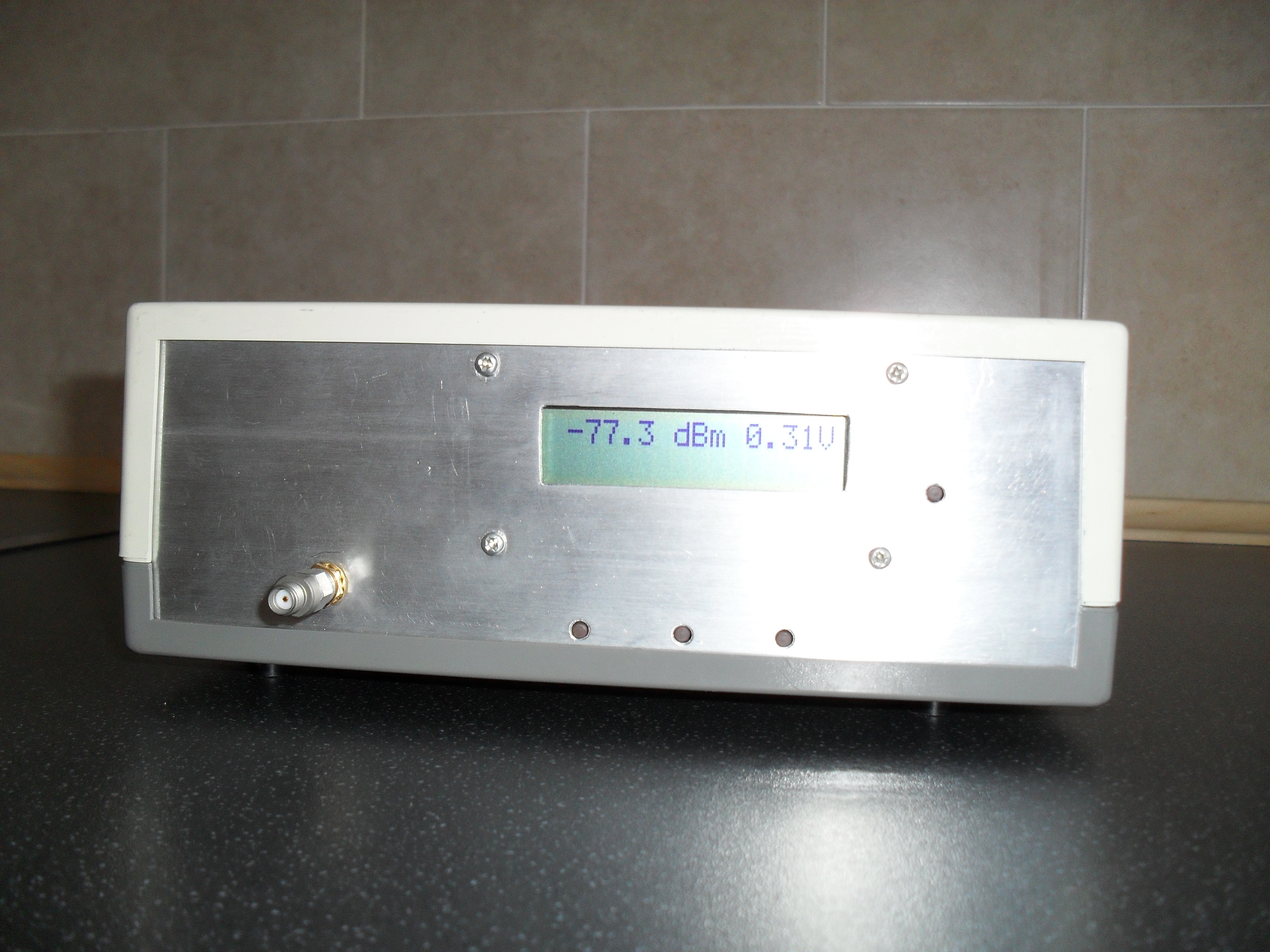
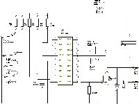
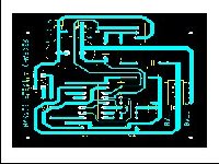
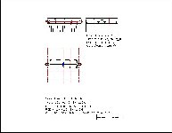
This is my version of the " KA7EXM PIC based mW Power Meter " as featured in the ARRL Amateur Radio Handbook 2007, I decided to build it as part of the collection of test gear for my Amateur Radio station so that I could test my Table Top 200 Watt 145MHz Amplifier ( and other future projects ) the boards were drawn up to incorporate long reach push button switches rather than the seperate switches of the original design so that a single module for the PIC and LCD display could be fitted to the front panel of the instrument with just four screws .The RF head was designed to fit in a standard tinplate box available from a couple of UK suppliers. I also changed the 78L05's in the original design for equivalent LDO regulators to enable me to use a " NiCd / NiMH " rechargeable battery which is normally 8.4 volts, the software being latest version ( V2.0.0 ) downloaded from the KA7EXM .net website ,.Having built & tested the unit , I've decided to investigate the possibilites of using other similar power detectors available to make a similar unit for VHF / UHF upto 2.5 GHz to cover the 2m ,70cm, 23 cm and 13cm / 2.4 GHz bands. The new Power Meter RF head will use the " Hittite " HMC713MS8 log amp / detector IC which although it has a reduced dynamic range compared to the AD8307 of the original design , but a broader frequency response together with a nearly flat sensitivity mV / dB across the frequency range 100MHz - 2.5 GHz of about 17mV , the addition of a small attenuator ( of approx 10dB) whilst decreasing the sensitivity has the advantage of improving the return loss ( VSWR ) and protecting the RF detector from accidental overload .The calibration of the unit following the procedures in the ARRL handbook as per the original .
This page last updated 21st Oct 2009